Question How do I wire my Samsung Sun Boards Properly?

jaguarlax

Tactical Gardener
Staff member
Administrator
Moderator
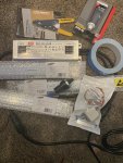
Almost there guys. I am really just double checking to make sure the diagram I have is correct before I start wiring... all of the diagrams I have are for 6x or 4x setups.Thanks to @JL2G I know the numbers are correct. Just gotta get the electricity to flow properly now. In this case Would the HLG and the XLG driver be wired the same way if every thing else in the diagram is identical?

Side note: this plug needs to get clipped. Wire is at a minimum tonight so I would like to try and do this once :)
EA79E59F-3D0C-499E-8C42-B676BD9AC8FC.png
1ACCDAD4-BA95-4508-BBB4-FEC3C850F015.jpeg
2979ED17-BB94-4572-B965-20E6340589A9.jpeg
1B2660A8-B9BD-4F42-A51B-8047C53FB4CA.jpeg
 
Solution
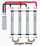
Here's the pic I went and pulled from that other thread.
You'd just add another 3rd set of them for a total of 6 boards, installed in the same as the first two were wired.
15048a1.png
With the third set though you would not be able to max the leds out.
You'd be maxing the driver out first. Likely setting off the hiccup mode.
You'd want to dial the set screw for the internal pot back just shy of the drivers limits using a multimeter to do so. Or trial and error. Lol.
If wiring just the four boards you'd still want to dial the screw back as well just to limit what the driver can send to them, so as not to overpower the diodes. With proper cooling they'd probably even take the overpower. Lol
I just considered that you may not be running the same driver as me.... what model did he send @Buzzer777 ?


@MichiganGrampa glad youre here, I am NOT the electrical savant...thats for sure....maybe you can shed some light

I'd have to see all the numbers on the output side. I can see that it's a 48v driver, but I can't make out the rest. I'd need to know the output amps and the forward voltage on the LED strips. However, from what I've read @JL2G has you headed in the right direction.

I know there's a big cost difference in materials, but I'd personally use aluminum angle vs iron for the frame pcs.
Keep it all as light, lol, as possible.

Where I've mounted frames to heat sinks I've just drilled through the sink in a spot not taken up by the led and used rivets to lock things in place.
Screws will work as well, or small bolts and such. I just prefer rivets as they won't come loose, no threads to strip out.
Add a cross brace to keep things squared up, and lock them in all solid.

You can use steel to mount heat-sinks but the heat-sink itself should be aluminum or copper due to the thermal properties of these 2 metals over steel.

Again, he's giving you excellent information ...
 
I found the numbers on the LED strips. 24V dc running at .7-.9 amps. Just as he has said, you would want to run 2 boards in each series. The number of amps you run should be roughly 60% of the driver's rated output. That being said, running 3.6 amps on a driver rated for 4.5amps or higher would provide max output to each 2 board series.

Edit: This is assuming that you're building a 4 strip light.
 
Here's the pic I went and pulled from that other thread.
You'd just add another 3rd set of them for a total of 6 boards, installed in the same as the first two were wired.
View attachment 11597
With the third set though you would not be able to max the leds out.
You'd be maxing the driver out first. Likely setting off the hiccup mode.
You'd want to dial the set screw for the internal pot back just shy of the drivers limits using a multimeter to do so. Or trial and error. Lol.
If wiring just the four boards you'd still want to dial the screw back as well just to limit what the driver can send to them, so as not to overpower the diodes. With proper cooling they'd probably even take the overpower. Lol

Wire them like he's shown you above. By using the jumpers like he's shown you, your two 24v boards are wired in series and are pulling 48v @ 1.8amps (1800 milli-amps) each.
 

JL2G

Jesse Loves 2 Grow
Staff member
Moderator
Q-36 Space Modulator
Wire them like he's shown you above. By using the jumpers like he's shown you, your two 24v boards are wired in series and are pulling 48v @ 1.8amps (1800 milli-amps) each.
Yep, what he said. ?
Weird, I haven't been getting my notifications or I'd of answered much quicker.

Series and parallel wiring can be combined depending on how it's done.
Most of the leds lights these days use a combination of both wiring methods to achieve the FV and or amps needed for operation with low power to mid power diodes.
Kinda catching up on what's being discussed, where are we at with this dilemma and how can I help? Lol
 

JL2G

Jesse Loves 2 Grow
Staff member
Moderator
Q-36 Space Modulator
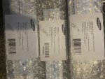
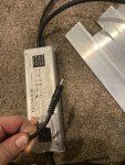
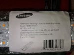
Almost there guys. I am really just double checking to make sure the diagram I have is correct before I start wiring... all of the diagrams I have are for 6x or 4x setups.Thanks to @JL2G I know the numbers are correct. Just gotta get the electricity to flow properly now. In this case Would the HLG and the XLG driver be wired the same way if every thing else in the diagram is identical?

Side note: this plug needs to get clipped. Wire is at a minimum tonight so I would like to try and do this once :)
View attachment 11593
View attachment 11591
View attachment 11592
View attachment 11594
That hlg would not be wired the same as you would the xlg one in the pic. One would be parallel only, the hlg, the xlg would be parallels of series wiring. They have different fv that they're working with.
 

JL2G

Jesse Loves 2 Grow
Staff member
Moderator
Q-36 Space Modulator
@JL2G
I wired up 2 of my strips like this picture. They didn't work. But when I removed the jumpers in the lower half, they both light up fine and function with the dimmer. TBH..I never understood why they were wired both in parallel and the jumpers in series. I haver other QBs..some in Parallel and some in series..but not both on the same boards. I will find my Kill-o-Watt and see what they are putting out.
I didnt see a pic attached to see what you've got there.
I will say though that one of my sets of qb's has a jumper on the board. It's because that specific board I have is made to be switchable for portions of it. (Uv, IR, and deep reds)
The jumper on mine just makes it so they all run as one. Maybe you've got the same style, and or the wire was just put in the wrong place by manufacturer.
Throw some pics up and lemme take a look and well see what we see.
 

Buzzer777

In Bloom
I didnt see a pic attached to see what you've got there.
I will say though that one of my sets of qb's has a jumper on the board. It's because that specific board I have is made to be switchable for portions of it. (Uv, IR, and deep reds)
The jumper on mine just makes it so they all run as one. Maybe you've got the same style, and or the wire was just put in the wrong place by manufacturer.
Throw some pics up and lemme take a look and well see what we see.
I have 2 strips wired in Parallel with no jumpers using an HLG-240H-48B. All is working fine this way, but when I add in the additional 2 strips..I will revert to that sketch with the jumpers. I bought the same strips (different spectrum) that @jaguarlax has, and he recommended me to the vendor as well.
 

JL2G

Jesse Loves 2 Grow
Staff member
Moderator
Q-36 Space Modulator
I have 2 strips wired in Parallel with no jumpers using an HLG-240H-48B. All is working fine this way, but when I add in the additional 2 strips..I will revert to that sketch with the jumpers. I bought the same strips (different spectrum) that @jaguarlax has, and he recommended me to the vendor as well.
That seems very odd to me.
So if I have this right you have two 24v strips wired in parallel to a HLG-240-48v driver and it's working fine? Hmmm
Can you send a pic of the led strips data info on the edge of it it should be listed.
 
Yep, what he said. ?
Weird, I haven't been getting my notifications or I'd of answered much quicker.

Series and parallel wiring can be combined depending on how it's done.
Most of the leds lights these days use a combination of both wiring methods to achieve the FV and or amps needed for operation with low power to mid power diodes.
Kinda catching up on what's being discussed, where are we at with this dilemma and how can I help? Lol

Exactly, you will then wire your 2-board series in parallel to the driver. The end results should be pulling 3.6 amps @48v DC. This is where you use the trim pots behind the rubber plug to adjust the amperage down.
 

Buzzer777

In Bloom
Exactly, you will then wire your 2-board series in parallel to the driver. The end results should be pulling 3.6 amps @48v DC. This is where you use the trim pots behind the rubber plug to adjust the amperage down.
Mine is the B model and had a dimmer pot already attached to the leads. I always like the adjustment of the pots way better than the internal pots.
 

JL2G

Jesse Loves 2 Grow
Staff member
Moderator
Q-36 Space Modulator
Top Bottom