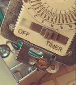
Electrical help, please.

Skunky Dunk Farms

Cannabinoid Receptor
View attachment 138025
I believe this ( highlighted in purple) multi-stranded wire is grounded, and attached to the neutral bus bar.


I got this.
View attachment 138024

The root issue I have is this outlet. It will light the tester, but the outlet does not work. View attachment 138023


This panel services my detached garage. As it was when I moved in , the right side is all outlets. Left side is all lighting.

I pulled the wiring down from the ceiling and installed that outlet in order to split the grow room load across two breakers.

So as it is, the only thing really drawing from that branch is the 1K HPS. It was working just fine, when used in February.

Getting chilly these days. I need to get that outlet working. I saw the char marks and I know something is amiss.
That black taped wire is a neutral.
I do not see an incoming/isolated ground coming in. Only grounds from circuits to a screw in the box.
This still doesn't mean the box is technically grounded.
You should havs an additional ground wire going back to your main breaker panel where it would terminate at the main buss.
Only a main should have combined ground and neautrals.

To try not to cause more confusion lol, a 12/3 type romex wire has 4 conductors.
2 lines, 1 neutral and 1 bare ground.
 

WillieP

In Bloom
Jewels,
The picture in post #11 of your overheads shows a 3-wire system.
The incoming power has three wires, 2 hots and a neutral.
That will be entering your weather head and going to your meter base through the conduit mast.
At the meter base the incoming neutral will be bonded (joined) to the grounding conductor that is connected to your ground rod.
From the meter base to the panel there will now be 4 conductors, 2 hots a neutral and a ground.
The same picture shows a free air cable that is traveling up the outside of your mast that is the feed to the lower overhead that feeds your remote sub-panel.
That shows that there are only 3 conductors in that overhead.
In a perfect world, there would be 4 conductors in that overhead, 2 hots, a neutral and a separate ground.
That is not the case here. If you care what to call that uninsulated overhead wire, you will need to follow the feed cable for the sub-panel back to the main panel and see where it is landed. Either on the neutral bus or the ground bus.
(But at that point they are electrically the same point, and it doesn't make a difference what we call it.)
The moral of the story is that it was very common at one point in history, to just use a 3 wire overhead to install a remote sub-panel. In fact, it was common to drive a separate ground rod to ground the sub-panel. This is not the currently approved method. It will create what is called ground loops, but that is a whole different topic.

All of that to say, that this has nothing to do with the fact that your light isn't working.
Is your out building's sub-panel wired up to current NEC code? No
Does that have anything to do with why your light is not working? No

So, how do we troubleshoot your light issue?
I would first recommend moving your light to a known functional outlet and see if your light works there.
This will prove if the problem is just in the light or in the outlet.
If the light works properly in a different outlet, then next I would use your meter as @M48 suggested to take voltage readings at the outlet in question.
Report back what you find, and we will go from there.

I hope that help clarify things. We'll get it figured out!

Cheers,
WillieP
 

Skunky Dunk Farms

Cannabinoid Receptor
I'll just give a quick example of a ground loop scenario.
This is a real world issue in my house from a previous "electrician " doin work "wrong".
When my washing machine is running in the wash cycle the overhead light in that room surges up and down slightly in brightness, this is caused by a "ground loop" situation where they didn't isolate the ground in the service box for the utility room. So the surging of the transmission in my washer loads the line through the motor back through the ground to the main instead of the neutral as it should.

,,I need to fix that lol.

Oh, and yes, Fluke is a great friend!
 

Jewels

Tilts at Tables
Thanks, me friends!
As a follow-up, I was able to resolve this issue.

Pretty simple really, I promise a licensed professional at big sack of weed, and he came over and fixed it.

Dirty/corroded connections in the transmission lines, between the house and the garage. The circuits pretended to be there, but they were incapable of carrying any amperage.


On to new things.

The heater I use to keep the garden warm while the lights are off is a binary unit. I plug the heater in and it turns on. I unplug it and it turns off.

I have been using a timer to regulate the temperature.
When it is near freezing I run four × one hour duty cycle, on.
When I expect colder temperatures, I increase the duty cycle. Near -30 Celsius I am 80% on, over the 12 hours.
It is a real dance.
It is a real pain in the butt.
It is soon to be a thing of the past

I coughed up the $7, and purchased a remote thermostat.
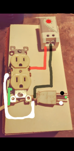
I would like to ask for help, in wiring it.

Goals:
I want the sensor mounted closer to the ceiling.
I want the plug to be hot, when the temperature falls too low.
I want to build a 'power bar' that only supplies power, when the temperature falls too low
Capture+_2023-11-15-14-08-09~2.png

I want to wire a male extension cord to the outlet.
I want the outlet to be hot, at the thermostats demand.

That is a 110v thermostat.
There are only two terminals on the unit.

Question: is this a property engineered circuit ?
Is it going to do what I want it to do ?
 

Willie

🍓 Crush Genetics 🍓
Thanks, me friends!
As a follow-up, I was able to resolve this issue.

Pretty simple really, I promise a licensed professional at big sack of weed, and he came over and fixed it.

Dirty/corroded connections in the transmission lines, between the house and the garage. The circuits pretended to be there, but they were incapable of carrying any amperage.


On to new things.

The heater I use to keep the garden warm while the lights are off is a binary unit. I plug the heater in and it turns on. I unplug it and it turns off.

I have been using a timer to regulate the temperature.
When it is near freezing I run four × one hour duty cycle, on.
When I expect colder temperatures, I increase the duty cycle. Near -30 Celsius I am 80% on, over the 12 hours.
It is a real dance.
It is a real pain in the butt.
It is soon to be a thing of the past

I coughed up the $7, and purchased a remote thermostat.
I would like to ask for help, in wiring it.

Goals:
I want the sensor mounted closer to the ceiling.
I want the plug to be hot, when the temperature falls too low.
I want to build a 'power bar' that only supplies power, when the temperature falls too low
View attachment 186603

I want to wire a male extension cord to the outlet.
I want the outlet to be hot, at the thermostats demand.

That is a 110v thermostat.
There are only two terminals on the unit.

Question: is this a property engineered circuit ?
Is it going to do what I want it to do ?
That looks good from here. I assume you have a mark for where the black line goes in on that t stat.
 

JL2G

Jesse Loves 2 Grow
Staff member
Moderator
Q-36 Space Modulator
Thanks, me friends!
As a follow-up, I was able to resolve this issue.

Pretty simple really, I promise a licensed professional at big sack of weed, and he came over and fixed it.

Dirty/corroded connections in the transmission lines, between the house and the garage. The circuits pretended to be there, but they were incapable of carrying any amperage.


On to new things.

The heater I use to keep the garden warm while the lights are off is a binary unit. I plug the heater in and it turns on. I unplug it and it turns off.

I have been using a timer to regulate the temperature.
When it is near freezing I run four × one hour duty cycle, on.
When I expect colder temperatures, I increase the duty cycle. Near -30 Celsius I am 80% on, over the 12 hours.
It is a real dance.
It is a real pain in the butt.
It is soon to be a thing of the past

I coughed up the $7, and purchased a remote thermostat.
I would like to ask for help, in wiring it.

Goals:
I want the sensor mounted closer to the ceiling.
I want the plug to be hot, when the temperature falls too low.
I want to build a 'power bar' that only supplies power, when the temperature falls too low
View attachment 186603

I want to wire a male extension cord to the outlet.
I want the outlet to be hot, at the thermostats demand.

That is a 110v thermostat.
There are only two terminals on the unit.

Question: is this a property engineered circuit ?
Is it going to do what I want it to do ?
That'd be correct the way you drew it in. Thermo switch being just like a light switch only interrupting the hot line.
 

JL2G

Jesse Loves 2 Grow
Staff member
Moderator
Q-36 Space Modulator
Well, Princess Auto did have a little dandy on sale last time I was there.
Once I get this HVAC situation figured out, I will be delving into that.

And not alone
🐰⚡🐰
Always something needs our attention. Lol
I've had many a sale prompt a home improvement of one sort or another.
Always so nice when it's finally done,and you can admire yer work, and or appreciate the benefits it brings. 😉
 

WODAHS

In Bloom
tempImaged9eGEj.jpg

Jewels@

This is what I use for a mobile thermostat.
Whether I'm running a Large Salamander Heater on a Job Site, or a Small Ceramic Heater in the Drying Room while the outdoor Temps are @24*F.
Set it & Forget it
 

Caddis

Zinger
Maybe I’m misunderstanding what the goal is?
I control my heater with an Inkbird, as well as my humidifier/ dehumidifier off another Inkbird.
 

Jewels

Tilts at Tables
Oftentimes building/repairing it himself
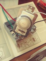
Thats the spirit!

$3.99 , Princess Auto Clearance
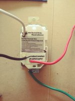
20240221_131215.jpg

Looks simple enough
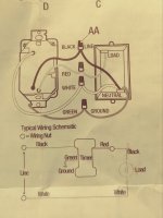
20240221_125928.jpg

These instructions are messing with me.
This timer was intended to replace a switch. I believe that is why the complete circuit is not Illustrated
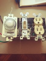
20240221_130010_(1).jpg

In the grand scheme of things,mains are attached to the timer. Timer provides power to outlet. Outlet is interruptible by switch.
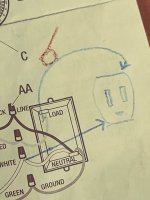
20240221_132650.jpg

The diagram does not address the downstream neutral wire. I believe I am correct in wiring it like this.
20240221_133244.jpg

Why ??

Because the moment I start messing with this, I lose.
20240221_131215_(1).jpg
That slider would only get me into trouble. Hoping to get a few years out of these things; it definitely looks like the weakest link, that slider might break the first time I touch it.
Synchronizing multiple timers is tricky business, and I am my own worst enemy. Looking to build two of these things ( one for each breaker) . Tired of messing things up, I want to get these timers set correctly, and never touch them again.
Rather than yoinking plugs, in order to make adjustments;
I want a nice, big, familiar, reliable switch.
 
Top Bottom